ATSyRA Building User Guide
1. Getting started
1.2. Starting a new building project
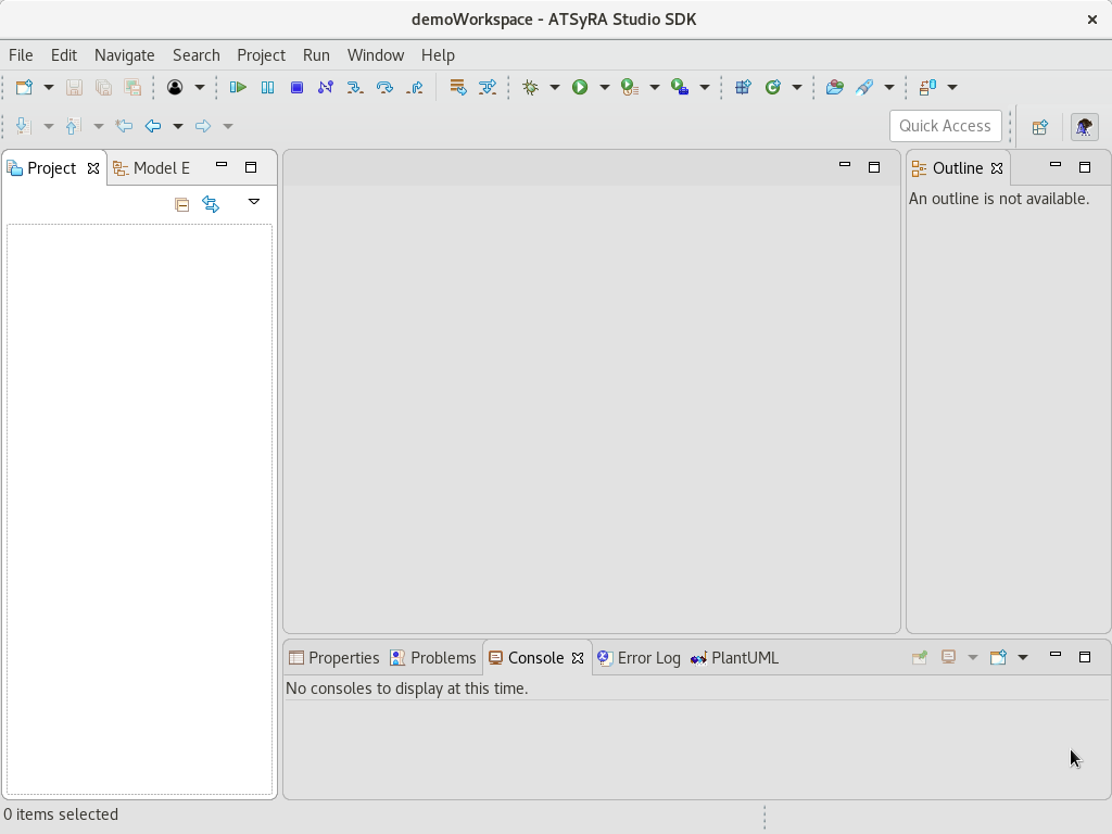
You are now ready to use ATSyRA. The interface is shown in Figure Interface. To create a new project, look for the menu and click File → New → ATSyRA Building Project. The window of Figure New project should show up.
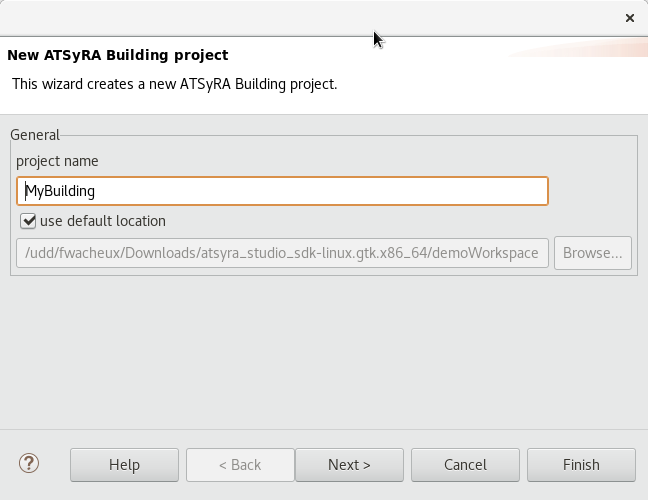
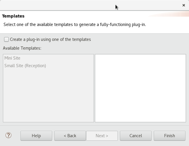
Choose a name for your project, and click Next. Pick a sample example if you want to try out the tool before creating your own building, and click Finish. Your project is now created.
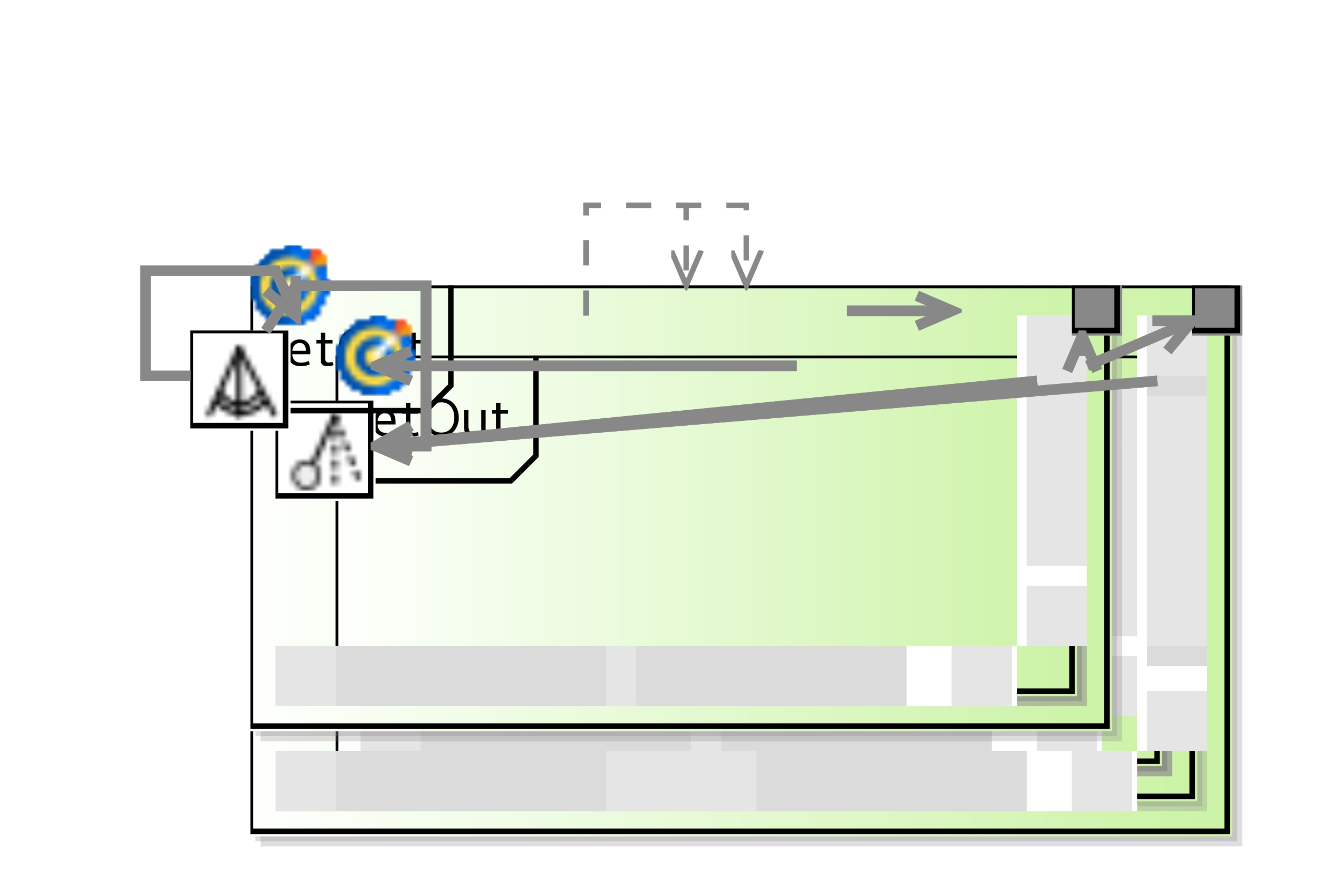
1.3. User Interface
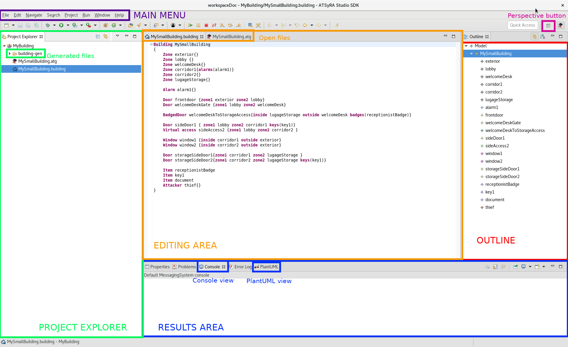
The user interface of ATSyRA is composed of several areas, as you can see in Figure Areas of the interface.
- Project Explorer
-
This is where your projects and files will appear. To show/hide the content of a project/folder, double click on it or use the little arrow on the left. One folder, named building-gen, will always appear in your projects, and will contain all the automatically generated files. Most of the actions specific to ATSyRA are available by a right click on the corresponding file, and choosing ATSyRA 4 Building in the menu.
- Editing area
-
This is where you can edit files. Open files by double clicking on their name in the project explorer. You can then select the file you want to edit at the top of the editing area, and write in it. Don’t forget to save your changes, as there is no autosave, using the Ctrl+s keys.
- Results Area
-
This is where the results of your analysis will appear. Most of them will show in the Console view, like reachability or correctness analysis. The PlantUML view will be useful to read attack scenarios.
- Outline
-
Shows the content of your building/goals in a hierarchical way. The outline will be explained later in the corresponding sections.
- Main Menu
-
Contains the usual File/Edit/… menus.
- Perspective Button
-
Use this button to change the perspective (window appearance). Make sure the selected perspective is the ATSyRA one, for a better user experience.
2. Specifying a building
The first step when using ATSyRA is to specify the building you want to study. If you used a sample when creating the project, you already have some existing files specifying a building. If you created a blank project, you will need to create the files manually. Right click on your project folder, and go to New → File. Create a file with extension .building. This will also create a building-gen folder where automatically generated files will appear. Now that you have the file, let’s specify the building. If you used a sample and want to try out the tools, you can skip this section.
Start by writing the following inside of your .building file:
Building <your_building_name> {

}
| Note that everything is case-sensitive when specifying the building, so be careful not to forget or add upper case letters. |
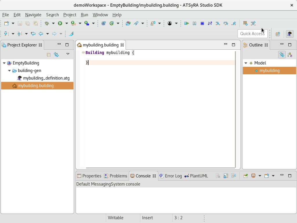
Your workspace should look like Figure Starting a building. You can now add elements into your building, as presented in the following of this section. These elements must be written inside of the brackets. You can add as many elements as you want, but keep in mind that a bigger building means that a lot more time and resources will be needed for the analysis.
2.1. Zones
A Zone is a location inside of the building where:
-
the attacker can go
-
some items can be found
-
some alarms can be deactivated
-
some alarms are watching
For example, a zone can be a room of the building, a safe, a key panel, …
Specifying a zone is very easy. Simply write the following inside of your building file:
Zone <your_zone_name> {
	alarms (<name_of_alarm_1>, <name_of_alarm_2>, ...)
}
<name_of_alarm_X> should be the names of existing and alarms (see the corresponding section for the definition of an alarm). Adding alarms is not mandatory, don’t put anything inside the brackets if you do not need them.
| It can sometimes be useful to add a fake zone with no accesses, where you can put items that cannot be picked, or alarms that cannot be deactivated. |
We will now see how to add elements like items or alarms inside a zone.
2.2. Items and skills
An Item is an element that the attacker might possess or that he can find during the attack, like keys or badges. They can then be used to unlock accesses. Items can also be objectives for the attacker, like documents to steal.
An item is written as follows:
Item <your_item_name>
Items can also be used to simulate skills. For example, an item named "Pick_simple_lock" could represent the possibility for the attacker to force a lock, and be a key to any door.
For now, items and skills cannot be used to deactivate alarms, but we might add this possibility in the future.
2.3. Alarms, cameras and security guards
An Alarm is an element that, when enabled, watches over some zones or accesses. If the attacker enter a zone or go through an access that is under alarm, the alarm will be triggered, and thus the attacker will be detected. To avoid being detected, the attacker will have to disable it.
An alarm is written as follows:
Alarm <your_alarm_name> {
	location <name_of_zone>
}
The location of an alarm is the Zone in which the alarm can be deactivated. If you do not want to offer the possibility to deactivate an alarm, feel free to use a fake, inaccessible zone.
You can also use alarms to represent cameras, which work in the exact same way, and even to depict employees or security guard. Think about them as alarms: they monitor the room they are in, and if they see something strange, they will get triggered and react. You can then think of how they can be "deactivated": triggering a fire alarm, reaching the cleaning supplies to not look suspicious, … This way of representing employees is just temporary, we will work in the future on a better way to add them.
For now, an alarm can only be deactivated in one location, but we might add the possibility to use several locations in the future.
2.4. Accesses
An Access is an element that allows the attacker to go from a Zone to an other Zone. The software allows to use several types of accesses, which are detailed below.
2.4.1. Virtual accesses
A Virtual access is an access between two Zones where no security elements are present: no key needed, no alarms, the attacker can simply go through it. Use this type of access for simple doors with no keys, or when there is no door at all.
A virtual access is written as follows:
Virtual access <your_access_name> {
	zone1 <name_of_zone_1>
	zone2 <name_of_zone_2>
}
<name_of_zone_1> and <name_of_zone_2> should be names of two already declared Zones.
2.4.2. Secured doors
A Door is an access between two Zones where some security elements are present: the attacker will need to deactivate an alarm or to get a key before going through it. Use this type of access for two-way doors where keys are needed or alarms are watching.
A door is written as follows:
Door <your_access_name> {
	zone1 <name_of_zone_1>
	zone2 <name_of_zone_2>
	keys (<name_of_item_1>, <name_of_item_2>, ...)
	alarms (<name_of_alarm_1>, <name_of_alarm_2>, ...)
}
<name_of_zone_1> and <name_of_zone_2> should be names of two already declared Zones. <name_of_item_X> and <name_of_alarm_X> should also be the names of existing items and alarms.
Note that keys and alarms are not mandatory on doors, but if neither are present, we recommend using virtual accesses in order to simplify the model and thus allowing a quicker analysis.
2.4.3. Secured doors with free exit
A Badged Door is a door where a key is needed to enter a room, but not to get out. This happens a lot in corporate buildings, where employees have a badge to be able to enter, but can exit freely. Use this type of accesses when a door is only secured in one way.
A badged door is written as follows:
BadgedDoor <your_access_name> {
	inside <name_of_zone_1>
	outside <name_of_zone_2>
	badges (<name_of_item_1>, <name_of_item_2>, ...)
	alarms (<name_of_alarm_1>, <name_of_alarm_2>, ...)
}
<name_of_zone_1> and <name_of_zone_2> should be names of two already declared Zones. <name_of_item_X> and <name_of_alarm_X> should also be the names of existing items and alarms.
| For the previous types of accesses, zone1 and zone2 could be exchanged without any problem. Here, a badge will be needed when going from the outside zone to the inside one, so they need to be correctly specified. Also note that alarms are optional, but there must be at least one badge. |
2.4.4. Windows
A Window is an access that do not require any keys, but that can only be opened from the inside of the building. Use this type of access for actual windows or for exit-only doors.
A window is written as follows:
Window <your_access_name> {
	inside <name_of_zone_1>
	outside <name_of_zone_2>
	alarms (<name_of_alarm_1>, <name_of_alarm_2>, ...)
}
<name_of_zone_1> and <name_of_zone_2> should be names of two already declared Zones. <name_of_alarm_X> should also be the name of existing alarms. No keys can be needed to open a window.
| Again, note that a window can only be opened from the inside zone, so the inside and outside zones need to be specified correctly, otherwise the window might open on the wrong side. |
2.5. Attacker
The Attacker is the person who will try to attack the building. You need to declare him, simply by giving him a name:
Attacker <your_attacker_name> {

}
For now, only one attacker is allowed. We will work on adding the possibility to have a team of attackers in the future.
2.6. Adding comments
You can add comments inside the building file to help you when reading the file again later. Comments can be written as follows:
// A comment on one line

/* Another comment on one line */

/* A comment on
several lines */
2.7. Outline
When the current file is a .building file, the outline area on the right side of the window gives a list of all the elements of the building, sorted by type: zones, alarms, accesses and items. A double click on one of the elements in the outline will bring you to its definition inside the .building file, which can be useful if you need to find an element in a large file.
2.8. Graphical view
ATSyRA provides a graphical view of the specified building. To have it to show, follow these few steps:
-
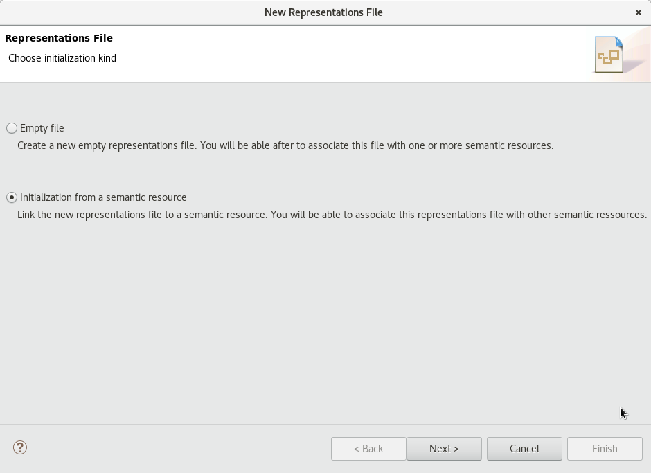
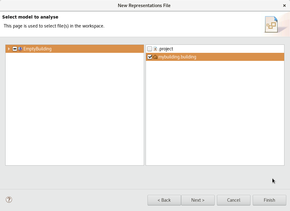
Right click on your project, and select New → Representations file. The window of Figure Representation file should appear. Pick the second option, "Initialization from a semantic resource", and proceed to the next page. Select your project, your building file should appear on the right part. Select it, and go to the next page. Choose a name for the file, and click Finish. When asked between ATSyRA Tree and ATSyRA Building, pick ATSyRA Building. You now have a new .aird file in the project explorer. *
-
Use the little arrow next to the .aird file in the project explorer to expand its content, until you find the ATSyRA Building Diagram. Double click on it, and the diagram of your building should show up.
-
The diagram should look like Figure Graphical view, not yet rearranged. The graphical view is still in beta, and it obviously needs to be improved. For now, you will need to rearrange the items manually to get it to be readable. To do so, simply drag and drop the items where you want them to be.
| TODO: Add a figure of a rearanged and readable building. |
2.9. Full building example
You can find below an example building file using all the existing features.
Building demoBuilding {

	Attacker attacker {}


	/* KEYS AND BADGES */
	Item Documents
	Item SafeCode
	Item EntryBadge
	Item OfficeKey


	/* SKILLS */
	Item Pick_lock_skill


	/* ALARMS AND CAMERAS */
	Alarm SafeAlarm {
		location DirOffice
	}


	/* EMPLOYEES */
	Alarm Director {
		location MeetingRoom
	}
	Alarm Employe1 {
		location MeetingRoom
	}
	Alarm Employe2 {
		location MeetingRoom
	}
	Alarm Employe3 {
		location MeetingRoom
	}


	/* ZONES */
	Zone Void { /* fake zone */

	}
	Zone Exterior {

	}
	Zone MeetingRoom {

	}
	Zone Corridor {

	}
	Zone Office1 {
		alarms (Employe1)
	}
	Zone Office2 {
		alarms (Employe2)
	}
	Zone Office3 {
		alarms (Employe3)
	}
	Zone DirOffice {
		alarms (Director)
	}
	Zone Safe {
		alarms (SafeAlarm)
	}


	/* ACCESSES */
	BadgedDoor FrontDoor {
		inside Corridor
		outside Exterior
		badges (EntryBadge)
	}
	Door Office1Door {
		zone1 Corridor
		zone2 Office1
		keys (Officekey, Pick_lock_skill)
	}
	Door Office2Door {
		zone1 Corridor
		zone2 Office2
		keys (Officekey, Pick_lock_skill)
	}
	Door Office3Door {
		zone1 Corridor
		zone2 Office3
		keys (Officekey, Pick_lock_skill)
	}
	Virtual access MeetingRoomAccess {
		zone1 Corridor
		zone2 MeetingRoom
	}
	Virtual access DirOfficeDoor {
		zone1 Corridor
		zone2 DirOffice
	}
	Door SafeAccess {
		zone1 DirOffice
		zone2 Safe
		keys (SafeCode)
		alarms (SafeAlarm)
	}
	Window SafetyExit {
		inside Corridor
		outside Exterior
	}
}
| TODO: Add a figure of the sirius view. |
3. Specifying attack goals
Now that you know how to specify a building, let’s see what we can do with it. First of all, you will need to specify goals, that is to say, the objectives of the attacker. This takes places inside an atsyra goal file, with extension .atg.
Such a file have been automatically generated from your building file, you should find it inside the building-gen folder.
| This automatically generated file might be generated again later, so do not modify it, as all your changes will be erased. |
In order to specify goals, you will need to create a new .atg file that will not be automatically regenerated. To do so, right click on your project, and go to New → File. Enter a file name with extension .atg, then click Finish.
Open your new file, and write the following:
import "building-gen/<name_of_the_automatically_generated_file>.atg"

AtsyraGoalModel {

}
The first line import the pre-existing .atg file to be able to use the definitions. Everything that you will later write in this file should be written inside of the brackets.
Now, let’s see how to specify goals.
A goal is divided into two parts: the initial condition, and the final condition. In practice, a goal looks like this:
pre :
	attacker.location = exterior
	and frontdoor.locked and not frontdoor.open
	and alarm1.enabled
	and key1.owner = attacker
	and document.location = interior
post :
	attacker.location = exterior
	and document.owner = attacker
	and not alarm1.triggered
Basically, this means:
- Initial condition (pre)
-
The attacker is outside, the front door is locked and closed, the alarm is watching, the attacker has the key, and the documents are inside.
- Final condition (post)
-
The attacker is outside, he has the document, and he has not been detected.
These initial and final conditions imply that the attacker needs to enter the building, find the document and get out without being noticed.
3.1. Variables
In order to write your goals, you will need to refer to the elements of your building. This section gives a list of all the variables that you can use to specify your goals.
3.1.1. Attacker
- <name_of_attacker>.location
-
the Zone where the attacker is
3.1.2. Item
- <name_of_item>.owner
-
True if the attacker possesses this item, False otherwise
- <name_of_item>.location
-
the Zone where the item is
3.1.3. Alarms
- <name_of_alarm>.enabled
-
True if this alarm is currently watching, False otherwise
- <name_of_alarm>.triggered
-
True if this alarm have detected the attacker, False otherwise
3.1.4. Accesses
Virtual accesses
There are no variables for virtual accesses.
Doors and Badged doors
- <name_of_door>.open
-
True if the door is open, False otherwise
- <name_of_door>.locked
-
True if the door is locked, False otherwise
Windows
- <name_of_window>.open
-
True if the window is open, False otherwise
3.2. Defaults
In order to simplify the process of goal writing, you can specify default settings for your initial conditions. These default settings will be usable in several goals, so it allows you to only write one time things that are always the same, like alarms being enabled and not triggered yet, or doors being locked.
Default settings are written as follows:
defaults {
	<name_of_setting_1> {
		<variable1> = <value> ,
		<variable2> = <value> ,
		...
	}

	<name_of_setting_2> {
		...
	}

	...
}
Add the definition of default settings in the .atg file, inside of the AtsyraGoalModel brackets.
3.3. Specifying a goal
Writing a goal is nearly the same as writing default settings, except that there are some operators.
- and
-
Used when several conditions need to be satisfied
- or
-
Used when one of several conditions need to be satisfied
- not
-
Used when a condition should NOT be satisfied
| Use parenthesis to ensure that the conditions are read in the right order by the tool. |
Goals are written as follows:
atsyragoals {
	Goal <name_of_goal_1> {
		pre:
			<variable1> = value
			and (<variable2> = <value> or <variable3> = <value>)
			and not <variable4> = <value>
			...

		post:
			...
	}

	Goal <name_of_goal_2> {
		pre with <name_of_default_setting>:
			...

		post:
			...
	}

	...
}
Add the definition of goals in the .atg file, inside of the AtsyraGoalModel brackets, under the default settings if you defined some.
When writing preconditions, you can either write all the conditions you need, or use a default setting. To do so, simply use pre with <name_of_default_setting>. This will use all the conditions already written in the default setting, plus the ones you add in the goal definition.
| If you use a default setting, and define in the goal precondition a variable that was already defined in the default setting, then the value that will be used is the one in the goal precondition. Thus, you can write your default settings and sligtly change them in goals if needed. |
| We recommand that you define as much variables as possible in the precondition, as any variable that is not defined leads to a bigger model, and implies that the analysis will take longer. |
3.4. Outline
As for buildings, the outline area shows the elements of your goals, and allow you to find them easily by double clicking on it (see Figure Outline for goals).
3.5. Checking reachability
Now that goals are defined, let’s check if they are reachable, that is to say, if there is a possibility for the attacker to go from the initial condition to the final one.
To do so, right click on your .atg file, and go to ATSyRA 4 Building → Check reachability of one goal. Select the name of the goal you want to analyze, and click OK.
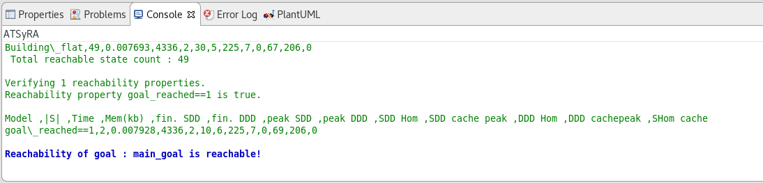
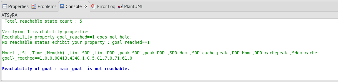
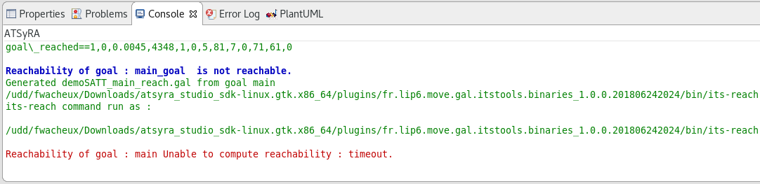
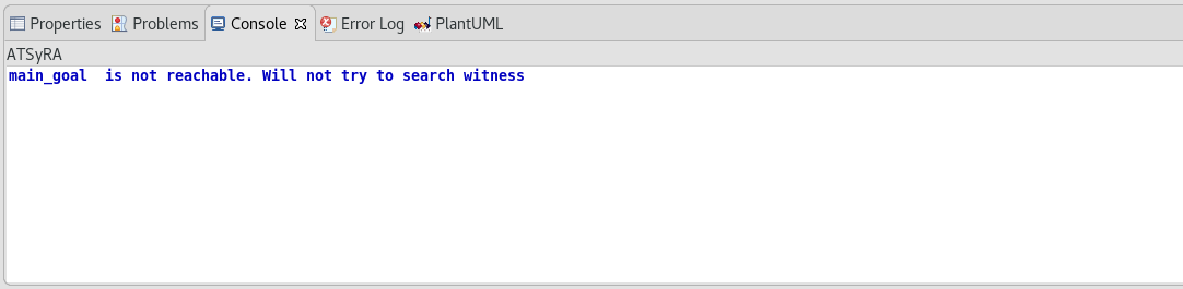
The results should appear on the console (see Figure Results of reachability analysis). Depending on the size of your building, the reachability analysis can take some time, so you might have to wait a bit.
| Sometimes, the default console shows up instead of the ATSyRA one, and the results do not appear. If this happens to you, look at the bottom right of the window. There are two little arrows, and the left one gives you a choice between Default MessagingSystem Console and ATSyRA. Pick ATSyRA, and your results will show up. |
There are three possible output:
-
Goal is reachable : the tool found a way to satisfy the goal, meaning that the specified goal is an actual threat.
-
Goal is not reachable : the tool checked that there was no way to satisfy the goal, meaning that there is no threat regarding these initial and final conditions.
-
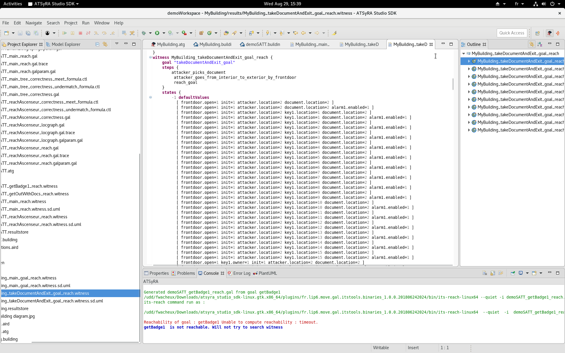
Time Out : the tool did not find an answer quickly enough and decided to stop the analysis. This might happen on large buildings. If you want the tool to try again for longer, you can modify the time limit as explained below and try again.
3.6. Extanding time limit
In order to avoid infinite computation, we had to put a time limit on all the functionnalities of ATSyRA. By default, all the tools timeout after 60 seconds. However, this time limit is not enough for big examples.
If your building is too big for the default timeout, go to Window → Preferences → ATSyRA → Computation, and change the maximum execution time.
3.7. Looking for attack scenarios
Knowing that a goal is reachable is good, but knowing how is better. ATSyRA provides a tool that gives witnesses, that is to say, existing scenarios that satisfies a given goal.
To get these scenarios, right click on your .atg file, go to ATSyRA 4 Building → Compute Shortest Wintess Scenarios, select the goal for witch you want to compute scenarios, and click OK.
| The goal need, of course, to be reachable. Otherwise, no scenarios can exist. |
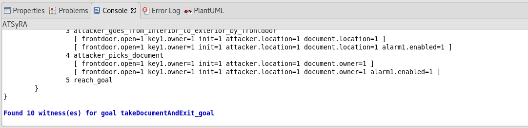
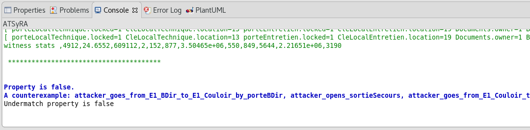
The results should appear on the console (see Figure Results of witness search). Depending on the size of your building, the analysis can take some time, so you might have to wait a bit.
| Sometimes, the default console shows up instead of the ATSyRA one, and the results do not appear. If this happens to you, look at the bottom right of the window. There are two little arrows, and the left one gives you a choice between Default MessagingSystem Console and ATSyRA. Pick ATSyRA, and your results will show up. |
There are four possible outputs:
-
Some witnesses were found: you can then read them or look at the sequence diagrams as explained below.
-
The goal is not reachable, thus no scenarios were found.
-
The goal is reachable, but no witnesses were found: we have encountered this situation a few times, and we are currently trying to understand why it can happen.
-
Time out : the tool did not find an answer quickly enough and decided to stop the analysis. This might happen on large buildings. If you want the tool to try again for longer, you can modify the time limit as explained previously and try again.
If the search of witnesses succeeded, a .witness and a .witness.sd.uml file should have been created inside the results folder. Let’s open the .witness file to see what is inside.
The main thing to look for inside the .witness file is the steps part: it gives a list of transitions that allow to go from the initial condition to the final one.
For small scenarios, the .witness file is easily readable. But in the case of large buildings, the witnesses might be too complex to read. To get a better understanding of a scenario, double click on the .witness.sd.uml file, and switch to the PlantUML view. This will show the sequence diagrams of the witnesses, which are easier to read.
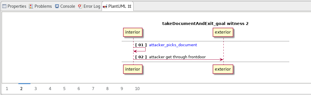
The sequence diagrams show the scenarios by aggregating the location of the attacker: each vertical line is a location, and the arrows are transitions that may or may not change the location of the attacker. With this representation, you can better understand what the attacker does in each location.
4. Specifying attack trees
An attack tree represents a goal of an attacker in a tree-like structure. The main goal is denoted by the root of the tree, and children of a node represent a refinement of the node’s goal into subgoals.
There are three types of nodes:
- AND
-
All the children must be completed.
- SAND
-
All the children must be completed, in the specified order.
- OR
-
One of the children have to be completed.
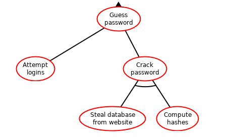
An example of an attack tree is given in Figure Example of an attack tree. In this example, the attacker wants to get a password. To do so, he can either try a lot of possible passwords until he finds the right one, or steal the password somewhere. And to steal the password, he need to steal the database and decode what’s inside.
4.1. Specifying a tree
Before specifying the actual tree, you need to define the goals that will appear in the nodes, as explained previously. There is no need to define a lot of goals at the beginning, just start with the main attack goal that will correspond to the root of the tree, and the first layer of refinement.
Once the goals are written, you can define a tree as follows:
trees {
	<name_of_tree> [<name_of_goal>] <OP> (
		<first_son>,
		<second_son>,
		...
	)
}
Add the definition of trees in the .atg file, inside the AtsyraGoalModel brackets, under the atsyragoals ones.
<name_of_tree> can be any name you want to give, <name_of_goal> must be the name of an existing goal, and <OP> is one of AND, SAND, OR.
<first_son>, <second_son>, etc. are other trees. You can either write everything inside of the main tree, or define them outside and call them. The second option might be better for large trees, since it will be easier to read this way.
Here is an example to better understand the nesting of the trees:
main_tree [main] SAND (
	reachElevator [reachElevator] SAND (
		getBadge [getBadgeElevator] OR (
			badge1 [getBadge1],
			badge2 [getBadge2],
			badge3 [getBadge3]
		),
		enter [enterElevator]
	),
	getOutWithDocs [getOutWithDocs]
)
And here is the same example with the trees defined separately:
main_tree [main] SAND (
	reachElevator,
	getOutWithDocs
)

reachElevator [getBadgeElevator] SAND (
	getBadge,
	enter
)

getBadge [getBadgeElevator] OR (
	badge1,
	badge2,
	badge3
)

badge1 [getBadge1]

badge2 [getBadge2]

badge3 [getBadge3]

enter [enterElevator]

getOutWithDocs [getOutWithDocs]
| The objective when writing the attack tree is not to write all of it at the beginning: we recommand only doing one layer of refinement, check the correctness (see below), modify the tree if needed, and pursue to the next layer only when the current one is correct. Otherwise, if the first layer of refinement is not correct, all the other layers might be incorrect too. |
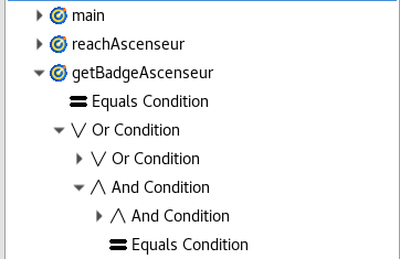
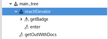
4.2. Outline
As for building and goals, the outline shows the elements of trees, and allow you to find them easily inside the atg file by double clicking on them. It also shows the nested structure of your trees (see Figure Outline for trees).
4.3. Graphical view
ATSyRA provides a graphical view of the specified trees. To have it to show, follow these few steps:
-
Right click on your project, and select New → Representations file. The window of Figure Representation file should appear. Pick the second option, "Initialization from a semantic resource", and proceed to the next page. Select your project, your .atg file should appear on the right part. Select it, and go to the next page. Choose a name for the file, and click Finish. When asked between ATSyRA Tree and ATSyRA Building, pick ATSyRA Tree. You now have a new .aird file in the project explorer. *
-
Use the little arrow next to the .aird file in the project explorer to expand its content, until you find the NestedBox Diagram. Double click on it, and the diagram of your tree should show up.
-
The diagram should look like Figure Graphical view, not yet rearranged. The graphical view is still in beta, and it obviously needs to be improved. For now, you will need to rearrange the items manually to get it to be readable. To do so, simply drag and drop the items where you want them to be.
| TODO: Add a figure of a rearanged and readable tree. |
4.4. Correctness properties
In order to verify that the tree is consistent, you can check so-called correctness properties, that compare the goal of a node with the goals of its children. In theory, these correctness properties check the following:
- Meet
-
There exists at least one attack that satisfies both the goal of the node and the combination of the goals of the children.
- Undermatch
-
All the attacks in the combination of the children satisfy the goal of the node.
- Overmatch
-
All the attacks in the goal of the node satisfy the combination of the goals of the children.
- Match
-
The combination of the goals of the children and the goal of the node gives exactly the same attacks.
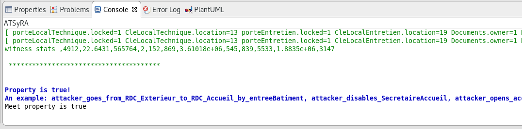
To check the correctness of your attack tree, right click on your .atg file, and go to ATSyRA 4 Building → Correctness → Check [xxx] property of tree. Select the tree you want to analyze, and click OK. The results will show up in the console. Note that the analysis might take some time, mostly for large buildings.
You can only check the Meet, Undermatch, and Overmatch properties with these steps. To check the Match property, simply check both the Undermatch and Overmatch ones. If both of them hold, then the Match property also holds.
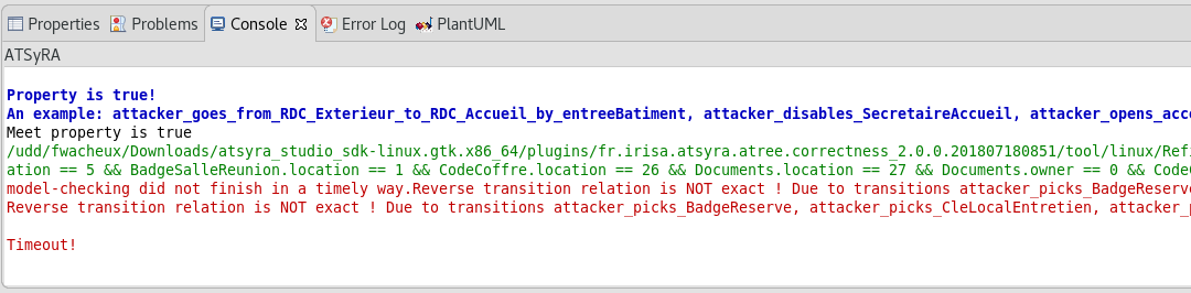
| Sometimes, the default console shows up instead of the ATSyRA one, and the results do not appear. If this happens to you, look at the bottom right of the window. There are two little arrows, and the left one gives you a choice between Default MessagingSystem Console and ATSyRA. Pick ATSyRA, and your results will show up. |
There can be three possible output:
-
Property holds
-
Property does not hold
-
Time out: the tool did not find an answer quickly enough and decided to stop the analysis. This might happen on large buildings. If you want the tool to try again for longer, you can modify the time limit as explained previously and try again.
Now that you can check correctness properties, let’s seet what the results of the analysis means for your attack tree:
- Match
-
If your tree have the Match property, that is to say if both Undermatch and Overmatch hold, the parent goal and the combination of the children depicts the exact same attacks. This means that uour refinement is correct, and there is no need to modify it.
- Overmatch
-
If your tree have the Overmatch property but not the Undermatch one, this means that your refinement includes the parent goal, but it adds some other attacks. This means that, if you decide to apply countermeasures to block the goals of the children, you might defend against scenarios that are not attacks. This is not a big problem, as long as you don’t use expensive and useless countermeasures.
- Undermatch
-
If your tree have the Undermatch property but not the Overmatch one, this means that your refinement contains only real attacks, but some have been forgotten. Thus, if you apply countermeasures based on the children nodes, you might still have flaws in your system in the end. This situation is not desirable, and we recommand working on the goals again.
- Meet
-
If your tree have the Meet property but not the Overmatch and Undermatch one, this means that your refinement somehow corresponds to the main goal, but you added and forgot some attacks. This is definitely not desirable, as you cannot get any useful informations on the actual threats, and we recommand working on the goals again.
- None
-
If your tree have none of the four properties, this means that your refinement have nothing to do with the parent goal. You should work on the goals again.
4.5. Counter-examples
When the tool finds that a property does not hold, it will look for a counter example, meaning an attack scenario that is in contradiction with said property. The computation of counter examples can be difficult, so sometimes the tool will not succeed in finding one, but most of the time it will give one.
You can use this counter example to understand why the property does not hold, by comparing the given scenario with your goals and trying to see where the problem is.
5. Additional tools: help for the design of attack trees [BETA]
We are currently working on some new tools meant to help for the design of attack trees by providing informations about which items are mandatory, i.e. the items that the attacker needs to pick up in every existing attack scenario, or locations where the attacker needs to go. These tools are still in beta, which means that they are integrated in ATSyRA, you can try to use them, but they might give you an error or crash.
5.1. Useful items
The usefull item tool allows you to check which items are mandatory, and which ones the attacker can not pick during his attacks.
To use this tool, right click on your .atg file, and go to ATSyRA 4 Building → Compute the necessary items for one goal. Pick the goal you want to analyze, and click OK. The computation can take some time, mostly when there are a lot of items in your building specification.
If the computation succeeds, four lists of items will show up in the console:
- Mandatory
-
The items in this list must be picked by the attacker, otherwise he cannot perform his attack.
- Already Possessed
-
The items in this list are possessed by the attacker in the initial condition, and the tool cannot check if he actually uses them or not.
- Never Picked
-
The attacker never picks these items, meaning that the attacker never uses them, in any attack scenario.
- Other
-
The items in this list are sometimes picked by the attacker, and sometimes not. This means that he can use them during his attack, but he doesn’t have to.
| Sometimes, the default console shows up instead of the ATSyRA one, and the results do not appear. If this happens to you, look at the bottom right of the window. There are two little arrows, and the left one gives you a choice between Default MessagingSystem Console and ATSyRA. Pick ATSyRA, and your results will show up. |
The results of this tool can help design the attack tree: if you know that an item is never used, then it should not appear in your attack tree. On the contrary, if an item is mandatory, then you could have a node who’s goal is to pick this item.
5.2. Location graph
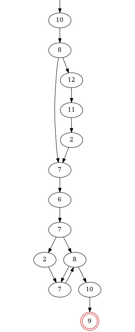
The location graph tool computes a graph representing all the scenarios for one goal, in terms of locations, or zones. An example of location graph is given in Figure Location graph. In this example, the attacker starts in location 10, and then goes to location 8. There, he has two choices: either reach location 7 directly, or do a little detour before. He then continues until he reached location 9, which is the final one. The locations in the graph are given by their internal id, but don’t worry: we provide the conversion table between the numbers and your zone names.
To use this tool, right click on your .atg file and go to ATSyRA 4 Building → Compute the graph of locations for one goal. Select the goal you want to analyze, and click OK.
If the computation succeeds, an image file will appear in the results folder. Open it to see the location graph.
In order to read the location graph, you will need the conversion table from internal zone ids to zone names. You will find this table into the building-gen folder, under the name <project_name>_<goal_name>_reach.gal.trace. Open this file to know the ids of your zones.
Now, you can use the location graph to get informations about the possible attack scenarios. Here are a few things to look for.
- Single possibilities
-
In the given example graph, you can see in the middle that all the paths lead to location 6. This means that location 6 is a mandatory zone: the attacker needs to go through this zone, in every possible attack scenario. Thus, reaching this zone can be a goal for a node of the tree.
- Loops
-
In the example, you can also see that before entering location 6, the attacker is in location 7. And when leaving location 6, the attacker goes to location 7 again. This is what we call a loop. This kind of loops means that there is something mandatory inside of location 6: a mandatory item, or an alarm to deactivate for example.
Using this tool can give you some precious informations about the general behavior of the attacker, and these informations can help you design your attack tree.